Good things are good to share, so head over to TheTechPrepper’s YT Channel for a lot of practical and valuable comms videos
And let’s not forget two other -but older- channels:
Comms Prepper & GuerillaComm
A Blog Dedicated to Survival and Preparedness Communications
Good things are good to share, so head over to TheTechPrepper’s YT Channel for a lot of practical and valuable comms videos
And let’s not forget two other -but older- channels:
Comms Prepper & GuerillaComm
Σημαντική Σημείωση: Το άρθρο αυτό γράφτηκε για την ενημέρωση και προετοιμασία των αναγνωστών. Μέχρι σήμερα (12/3/2024) η μπάντα ΔΕΝ έχει δοθεί για χρήση, αλλά αναμένεται οι διαδικασίες να ολοκληρωθούν συντόμως!
Πρόσφατα δόθηκε σε χρήση από τους πολίτες η μπάντα των GMRS. Δηλαδή μια ομάδα συχνοτήτων που υφίσταται από καιρό στις ΗΠΑ, και είναι διαθέσιμη σε ελεύθερη χρήση από το κοινό. Απαιτείται όμως η απόκτηση άδειας χρήσης.
Πρακτικά η χρήσης της μπάντας είναι κάτι ενδιάμεσο μεταξύ των PMR και των ραδιοερασιτεχνικών δικτύων, δηλαδή μεταξύ της εντελώς ελεύθερης και της αυστηρά καθορισμένης χρήσης.
Η απόκτηση άδειας χρήσης – ΧΩΡΙΣ εξετάσεις- όμως, είναι απαραίτητη γιατί στην ουσία ο χρήστης δημιουργεί ένα ιδιωτικό ραδιοδίκτυο πάνω σε δημόσιες συχνότητες.
Η GMRS σε Τεχνικούς Όρους
Η μπάντα τοποθετείται μεταξύ των συχνοτήτων 462 και 467 MHz, δηλαδή μέσα στα UHF, λίγο μετά της ραδιοερασιτεχνικής μπάντας των UHF.
Αντίθετα τώρα με τα PMR, οι σύγχρονοι ασύρματοι της GMRS έχουν πολλά κοινά με τους ραδιοερασιτεχνικούς όπως παρόμοιες συσκευές, παρόμοια ισχύ, αφαιρούμενη κεραίας και δυνατότητα εγκατάστασης ασυρμάτων σε αυτοκίνητο, σε “σταθμό βάσης”, αλλά και σε επαναλήπτη.
Για να δίνουν πιο κατανοητά όλα αυτά θα αναφερθούμε στα μειονεκτήματα και πλεονεκτήματα της μπάντας σε χρήση.
Μειονεκτήματα
Ίσως το μοναδικό μειονέκτημα της είναι ότι τοποθετημένη στα UHF, δεν συμπεριφέρεται καλά σε μέρη με βλάστηση γιατί η απορρόφηση της ακτινοβολίας από αυτή είναι μεγαλύτερη από τα VHF.
Αυτό όμως αντισταθμίζεται από την καλύτερη διάδοση μέσα στις πόλεις, λόγω των πολλαπλών αντανακλάσεων από τα κτίρια.
Κάποιοι βέβαια θα βρουν αποθαρρυντικό την υποχρεωτικότητα αδειοδότησης.

Πλεονεκτήματα
Η χρήση της GMRS μπάντας απαιτεί βέβαια αδειοδότηση όπως είπαμε, αλλά από την άλλη δεν απαιτούνται εξετάσεις. Επίσης αν εφαρμοστεί στην Ελλάδα ότι και στο εξωτερικό, τότε θα έχουμε και οικογενειακές άδειες, που θα καλύπτουν όλα τα μέλη της οικογένειας, κάτι πολύ χρήσιμο για τους preppers.
Πολύ σημαντικό πλεονέκτημα για την μπάντα αυτή είναι και η δυνατότητα χρήσης υψηλής ισχύος, έως και 50 Watt, αλλά ΚΑΙ συσκευών βάσης και mobile.
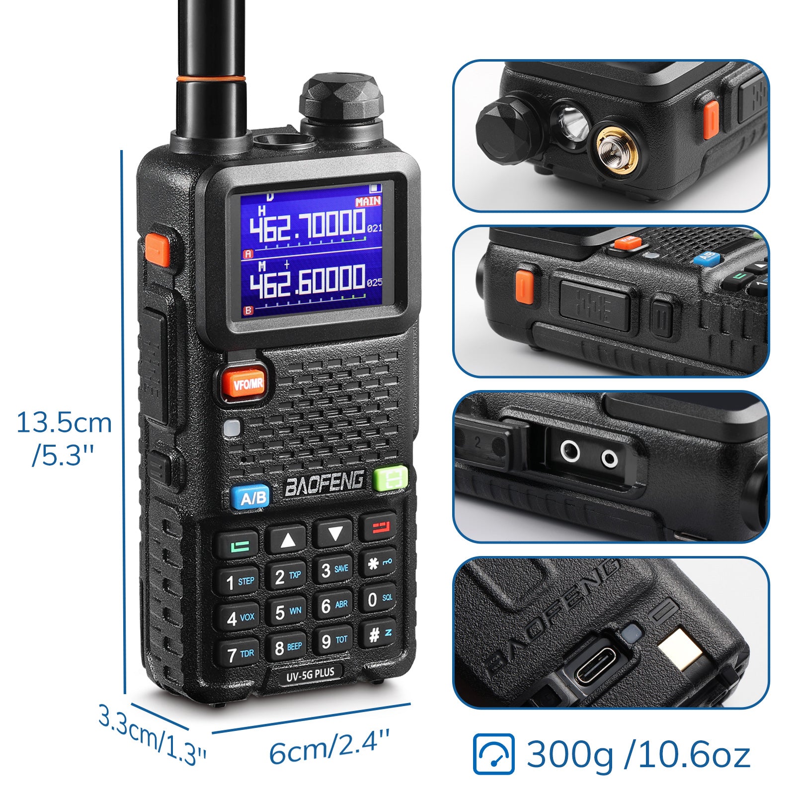
Ένα Baofeng UV-5G, αδερφάκι του UV-5Χ και αυτό στην μπάντα GMRS
Το άλλο σημαντικό είναι η χρήση αφαιρούμενης κεραίας. Έτσι ο χρήστης μπορεί να εκμεταλλευτεί τα πλεονεκτήματα των κεραιών βάσης, αυτοκινήτου κτλ.
Ακόμα πιο σημαντικό είναι ότι επιτρέπεται η χρήση επαναληπτών (Repeaters).
Σχετικά με την διάδοση, η μικρότερη εμβέλεια στο φυσικό περιβάλλον, βοηθά στην ασφάλεια των επικοινωνιών, ειδικά αν τοποθετηθεί στον ασύρματο πολύ κοντή κεραία με μικρό Gain.
Τέλος, σημαντική είναι και η διαθεσιμότητα συσκευών σε χαμηλές τιμές καθώς οι Κινέζοι κατασκευαστές ήδη προσαρμόζουν τα V/UHF μοντέλα τους στην κατάλληλη συχνότητα, διατηρώντας μάλιστα την συμβατότητα με τα αξεσουάρ.
Στα πρακτικά του θέματος λοιπόν, η μπάντα δεν διαφέρει και πολύ από την ραδιοερασιτεχνική μπάντα των UHF.
Μένει να δούμε αν στο μέλλον θα υπάρξει δυνατότητα ψηφιακών επικοινωνιών για μετάδοση θέσης, δεδομένων, γραπτών μηνυμάτων κτλ.
Παραπομπές – Πληροφόρηση
Few days ago i took the time to “field-test” this “Tactical” Dipole…
Not only I hang it from a tree, I also tried it as a backpacking antenna while hiking a short distance.
It works fine, transmission RST was great.
The photos will tell the story.

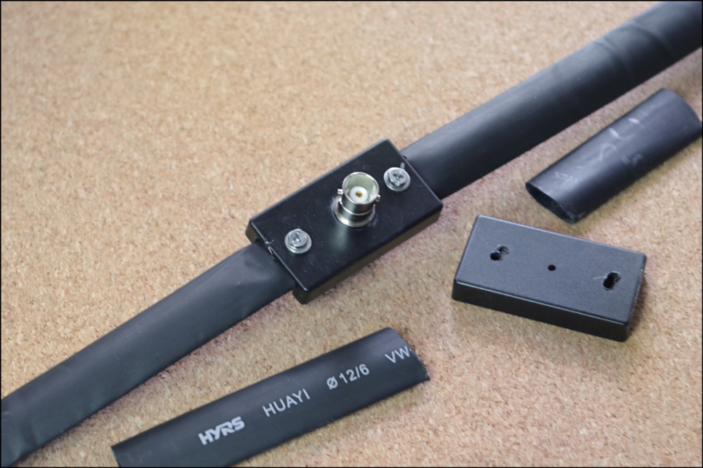
During assembly. While a stick was used to maintain the coax at 90degress to the dipole, I have already made a PVC pipe sleeve dor it, as shown at this pic.

Υeh, I know…. While part of the test was to use non-dedicated material, a few good xipties are in-order (the ties shown are the ones that hold the coax wound).

The dipole hanging… I used a Munter Hitch on the small carabiner to adjust the angle.

And the antenna mounted on my daypack.
(A better mounting method must be used. Eagle-eyed viewers will notice that the antenna is attached to the packpack zipper, and it extends below the small backpack.)
That is all for now.
If you liked the build, please share.
So… Trying to achieve a bigger resiliency I have been making extra connection cable for all my radio devices.
An extra one for the Surecom SR-112 was in order so I put myself into it. It turned out to be a night mare!
This cable connects to Radio with the well-known Kenwood bi-pin plug and to the SR-112 with a TRRS (4-pole) 3.5mm Jack.
Pinout is a shown in this diagram.

So I got me a TRRS splitter cable (headphones & mic) and changed out the female connectors to a 3.5mm and a 2.5mm stereo Jack. Minding the proper pinout.

The end product.

So I connected the two devices together to test my build, and…. No Worky!
I re-checked the pin-outs, all were well, but NO worky.
Then it downed me. Only some time earlier i had watched a Youtube video by someone that explained why the SR-112 does not work with home built cables.
Surecomm SR112 Repeater Controller Problem and Fix Video
Surecomm uses an abnormally long TRRS Jack, so using a regular one will not go as far to properly connect. Here is what it looks like.
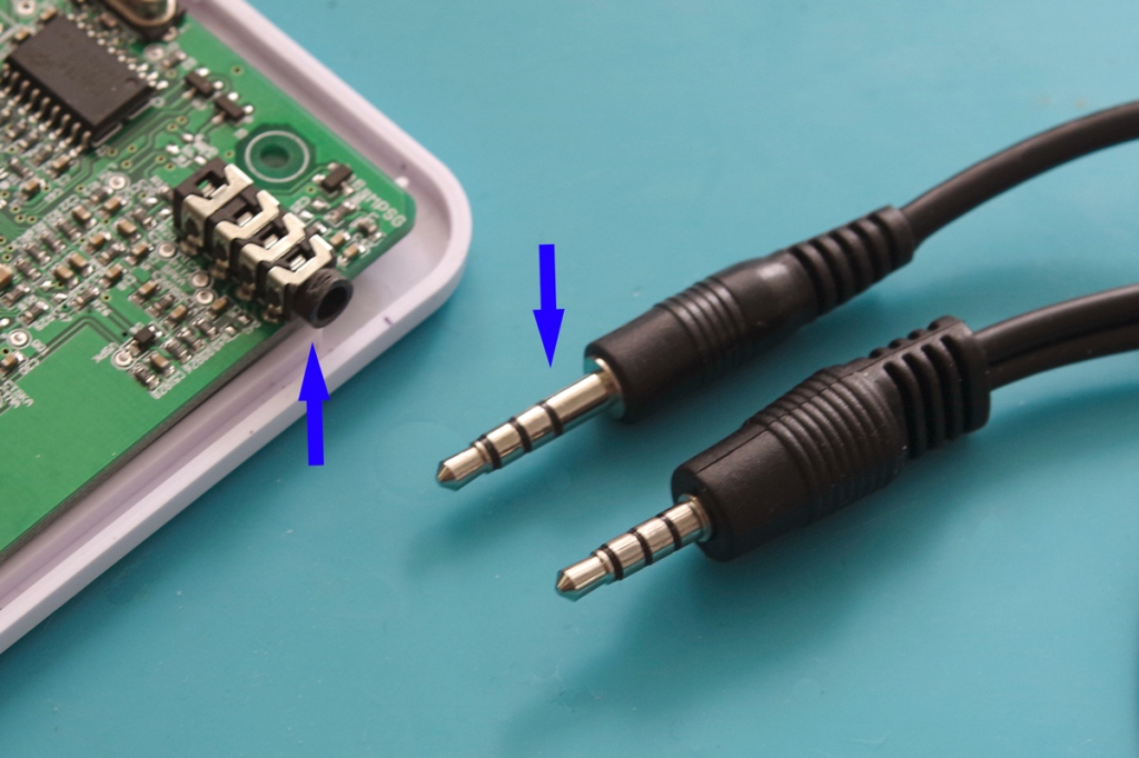
One arrow points to the Surecomm jack next to a regular one. The other one points to the SR-112 socket. Notice that there is a long rim that extends beyond the case, but trimming it is not enough. One would have to remove the faceplate and trim further.
But I will not give up. I have on order another splitter cable with a longer jack that seems to be of the proper length. This.

Wish me luck!
You are reading the SurvivalComms blog, so it would be natural to find posts that show builds made with non-specific materials, easily procured from Non-HAM shops.
And I feel it is innate to radio amateurs to make do, use and improvise when need be. It is another thing to prepare for a contest event and another in a scant resources situation. So one might have to do with what is readily available or easy to scrounge. In my case, I have already bought and used the last length of RG-58 cable available locally.
So, pending an online purchase, this is an antenna feed cable made by generic BNC Connectors and RG-59 cable pulled from security camera feed cable. Just THAT simple.

I know that there is some controversy of using 75-ohm cable with your radio, but the this coax will feed – for the time being- the 75-ohm Tape Dipole Antenna. Furthermore, it will allow me to experiment with different coax types of the same length. And yes, I will add a ferrite choke near the radio.
That is all for now, an interesting Build Fail article is on the make. Stay tuned!
Η κατασκευή αυτή βασίζεται στην ιδέα του Jeff’s Outdoors Page Half-Wave Dipole Antenna. Ουσιαστικά είναι το ίδιο, απλά αλλάχτηκε η υλοποίηση και προστέθηκε η δυνατότητα μελλοντικής αναβάθμισης.
Αρχή με τα Υλικά

1. Βίδες, Παξιμάδια, Ροδέλες και 2 λαστιχάκια μπαταρίας βρύσης. Πέρα από την συγκράτηση των σκελών του δίπολου, τα λαστιχάκια και οι ροδέλες χρησιμοποιήθηκαν για να κρατήσουν την φυσική καμπυλότητα των κομματιών της μετροταινίας. Διαφορετικά τα σκέλη θα πάρουν μια σημαντική γωνία ως προς το κάθετο.
2 & 3. Κουτί ηλεκτρονικών. Όλα τα κομμάτια συναρμόζονται εκεί. επίσης ένας κοννέκτορας BNC για Σασί (προτιμήστε Αρσενικό), και δακτυλίδια από καλωδίων (RCA, UHF, KO).
4. Τέσσερα κομμάτια (ανά δύο) μετροταινίας. Ξεκινήσαμε με το τυπικό μήκος που δίνει ο μαθηματικός τύπος του δίπολου, αλλά καταλήξαμε στα
5. Λωρίδες από εύκαμπτο υλικό συσκευασίας. Αυτά προστέθηκαν στις άκρες του δίπολου για να μπορεί να κρεμαστεί.
6. Πρεσσαριστά grommets (κορδονιών) για την συναρμολόγηση (Κάντε τις τρύπες αρκετά μέσα ώστε να έχετε ένα περιθώριο κοπής των σκελών).

Εδώ έχουμε το εσωτερικό του κουτιού που φαίνεται η συνδεσμολογία.
Tip: Μόλις καταλήξετε στη τελική κατασκευή, κολλήστε των κοννέκτορα BNC στο κουτί με εποξική κόλλα. Διαφορετικά θα έχει την τάση να στρίβει όταν αποσυνδέεται το καλώδιο μεταφοράς.
Το επόμενο βήμα είναι η κάλυψη του δίπολου με αυτοσυρρικνωμένο. Στα άκρα θα προστεθεί αυτοσυρρικνώμενο με κόλλα.
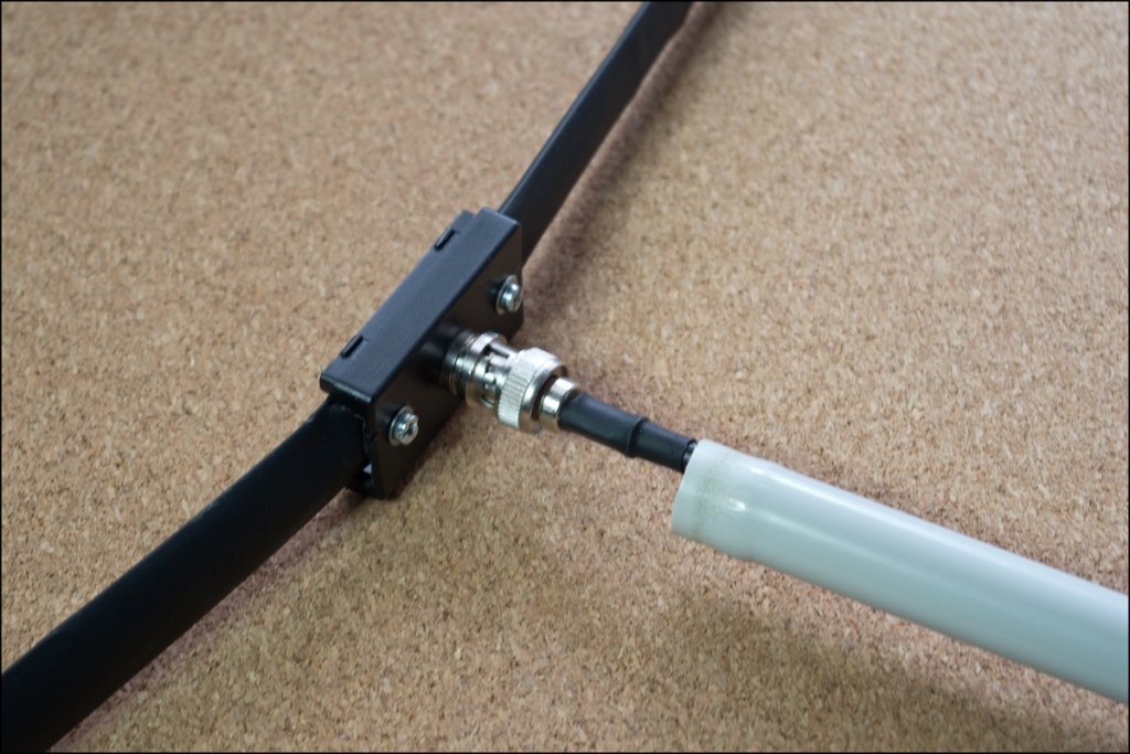
Για να μείνει το καλώδιο μεταφοράς κάθετο στην ευθεία του δίπολου προστέθηκε γύρω από το ομοαξονικό ένα κομμάτι σωλήνας PVC. Στη συνέχεια το δίπολο κρεμάστηκε από αυτό.
Και το δίπολο διπλωμένο (Φώτο από παλιότερη κατασκαφή).

Περιθώρια ΕξέλιξηςΣτο διαδίκτυο εντοπίσαμε μια κατασκευή του VK1NAM δίπολου για τα VHF που χρησιμοποιεί και Balun. Κάποια στιγμή το μέλλον θα δοκιμαστεί καθώς έχουν ήδη εξασφαλίσει τα υλικά.
Δοκιμή-Μετρήσεις
Η κεραία αναρτήθηκε σε ένα δέντρο 2 μέτρα από το εδάφους. Παρθήκαν διαδοχικές μετρήσεις ε ένα NanoVNA κόβοντας λίγο μήκος την φορά. Αφού βρέθηκε το σωστό μήκος, πάρθηκαν μετρήσεις και με ένα Στασιμόμετρο Red-Dot (μη καλιμπραρισμένο, που μετρά λίγο χειρότερα).

Σημαντικό είναι να προσέξετε το δίπολο να είναι κάθετο. Κάνοντας το λάθος να απομακρυνθώ λίγο τραβώντας το καλώδιο και δίνοντας μια μικρή κλίση στην κεραία, είδα μεγάλη διαφορά στην μέτρηση.
Αυτά προς το παρόν. Ελπίζω να βρήκατε την κατασκευή ενδιαφέρουσα.
This antenna build was inspired by Jeff’s Outdoors Page Half-Wave Dipole Antenna.
It is the same thing actually, just the materialization changes., And there is some room to improve.
But let’s start first with the build itself.
Parts Used
1. Bolts and washers, and 2 modified faucet sealing rings. The washers and the rings are installed between the two tape sections to hold their natural curvature. Then the sections are screwed on the electronics’ project box.
2 & 3. Electronics’ project box, panel mount BNC connector and ring terminals stolen from RCA and UHF connectors. This time it paid well to hoard such odd things.
4. Two sections of el-cheapo tape measure for each dipole part. The paint around the screw holes was removed for conductivity.
5. Blister packaging strips added to the dipole ends for hanging it.
6. Shoe string eyelets to fix the flexible blister sections onto the tape.
And this is how the innards of the box are assembled. Standard connectivity pattern. Tiny sections of wire soldered at the ends of the ring terminals.
BNC female panel connector. I regretted buying these, they are the opposite of the norm, thus a different cable or an adapter must be used. Better opt for a BNC Male connector.
A tip…Fix the BNC connector with some epoxy to the body. Clipping and unclipping the BNC male connector tends to turn the female one.
Shrink tubing is tucked inside the box opening. After the final testing and measurements it will be shrinked some, and the junction filled with gasket sealant.
BTW, the dipole ends will be finished with self sticking shrink tubing, for some measure of waterproofing.
Coax wire is connected and a 16mm PVC tubing section is passed over it. Its end has been enlarged to clip on the BNC connector. This way you will be holding a 1/4 wave length of coax perpendicular to the dipole itself.
The antenna in carry mode.
Room for Improvement
I have already acquired the materials to add a balun to it. I will be following VK1NAM’s build, and building a 2nd tape measure dipole for comparison.
it will take a while , but it will happen.
Testing
The antenna was “tuned” by a SWR meter and a NanoVNA in the field.
Its final length was finalized in situ, handing from a tree at a height of 2m. Then the antenna was disassembled and re-build at home.
It is a hassle lowering the antenna, removing the shrink tubing (expected to affect performance, trim some length, reinstalling the tubing and raising it up again. And DO take care to keep the antenna vertical. NanoVNAs are marvelous ‘ cos they are showing live how an antenna’s performance changes as height and inclination is changed.
NanoVNA measurements were done with the device calibrated at the Coax End. SWR meter ones were also taken, but with the antenna on. Please take this into account when comparing the two.
That’s all.
And if you feel you got something out of this build, please share it.
I admit, it is the EmComm part of HAM that I am more in favor off. And while by club failed in that regard, I managed to get accredited -as an amateur communicator – by the Civil Protection Service of my Country.
The raging wildfires of this August are quite far from me, but I thought it was a good reason to check my gear and organization.
Before going any further with the pick and lists, please let me describe the core elements of my organization:
That is not for the resiliency and the redundancy that is created, it is for the Murphy’s Law of HAMs, photographers, and maybe others. “You are going to need what you did NOT bring with you”.
So here it goes:
On Person Gear

Actually this is my main handheld radio accessory and support kit. From the upper left corner:
Car Kit
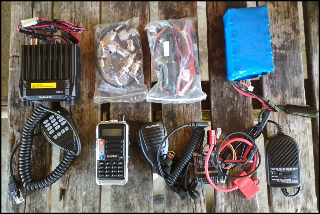
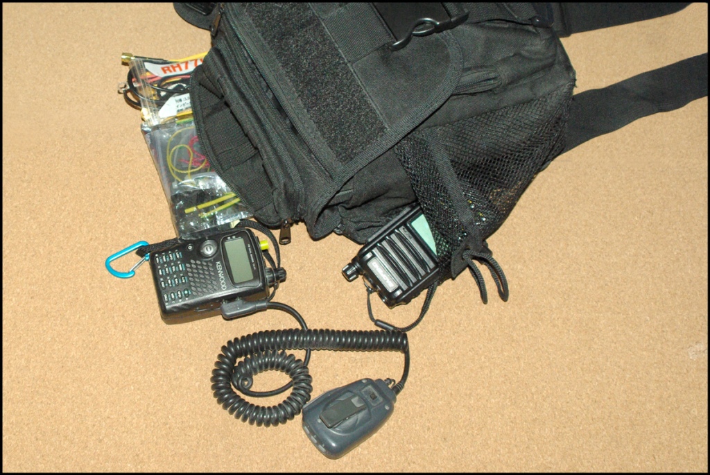
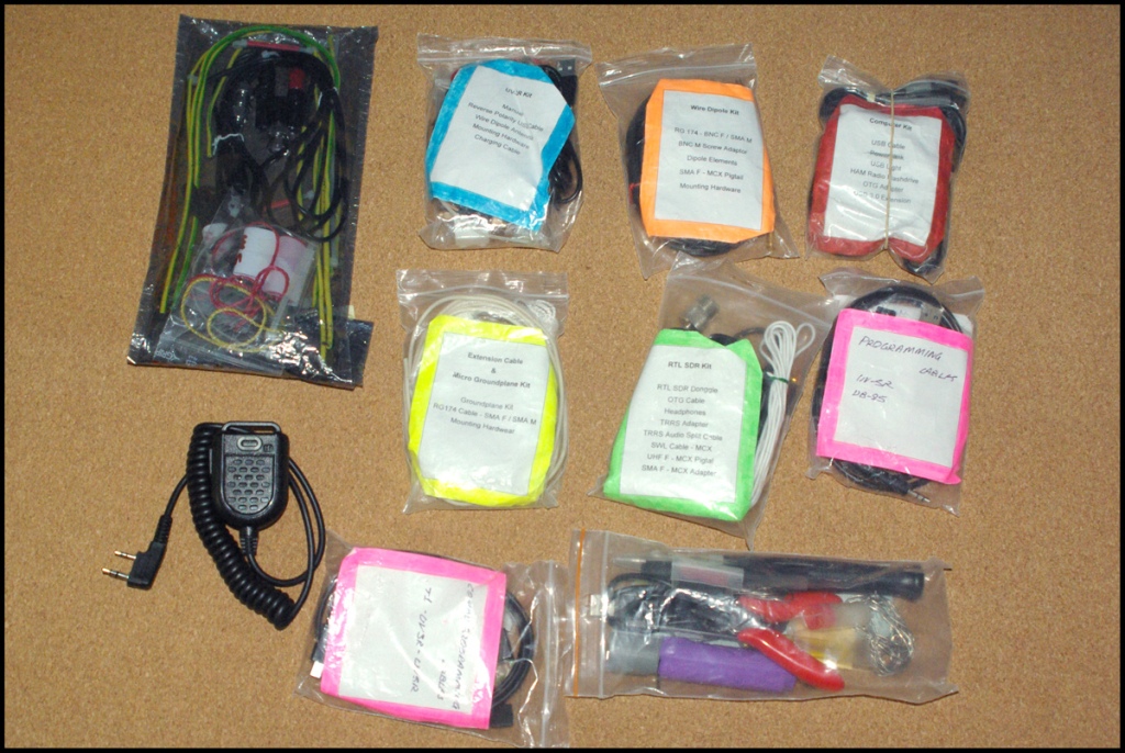
Level 1 “Ops” Kit
This is one step above showing up with a hand held, a better antenna, and an extra battery. It consists of the standalone prepackaged kits I talked before.
It is all carried in a Jumbo Versipack Clone.

Pretty exhaustive gear collection for sure…
In a future posting I will be covering the larger field gear kit. Stay tuned!
Το αρθράκι αυτό είναι μια αναπαραγωγή των πληροφοριών που διακινούνται σχετικά με το τις παρεμβολές στις επικοινωνίες στην Κούβα.
Καθώς η χώρα περνά μέρες ταραχών, φαίνεται ότι η κυβέρνηση έχει επιβάλει ολικό πληροφοριακό lockout, συμπεριλαμβανομένων και των ραδιοερασιτεχνικών μπαντών.
Παρόλα αυτά, Αμερικανοί ραδιοερασιτέχνες παρατήρησαν πως το σήμα των ψηφιακών modes περνούσε!
AmRRON operators on the east coast and southeast portions of the US were able to successfully exchange text messages and files using digital modes inside the affected portions of the band being jammed. The jamming did not prevent digital mode communications, which is another testament to digital modes.
Cuban Govt Blocks Internet — Jams Ham Radio Freqs
Αυτό επιβεβαιώνει τα ήδη γνωστά για τον ραδιοερασιτεχνισμό.
– Οι ραδιοερασιτέχνες θα βρούν την λύση στο πρόβλημα επικοινωνίας, είναι μέσα στο mindset τους αυτό.
– Πάντα να έχετε πολλαπλά και διαφορετικά εργαλεία στην “εργαλειοθήκη των ικανοτήτων σας.
Η Προσαρμοστικότητα γεννά Αποτελεσματικότητα.
It is for a fact that -crystaline solar panel perform the best when being placed vertically against the sun.
That is not always possible, especially when it comes to larger units, but it only takes some effort and diligence from the user to constantly align the smaller ones.
So I tried an placement experiment, at various angles that is. Λet’s see the difference in collected sun energy…
Solar Panel Placed Horizontally on the Ground
This is the lazy option for users, and an unavoidable one when it comes to camper vans etc.
At the time of the test (12:40 Daylight Saving Time) this position was close to being vertical to the sun also (maybe of a 3-5 degrees difference).
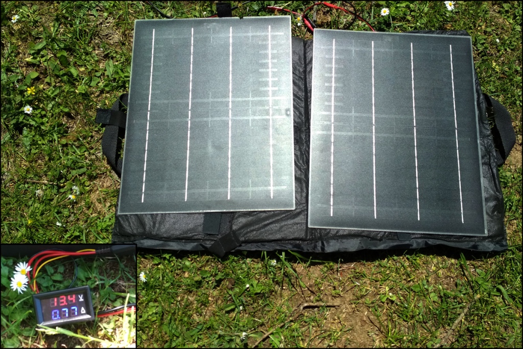
The volt/ampmeter showed 13.4V and 0.77A and that is 10.3W collected.
(please do not take this value at heart, it may be affected by my shadow when taking the meter’s pic)
Solar Panel Placed 45º Vertically to the Sun
This time the panels where placed to a 45º angle to the sun, the optimum angle for 10:00 and 16:00 hours for my location of 35º lat.
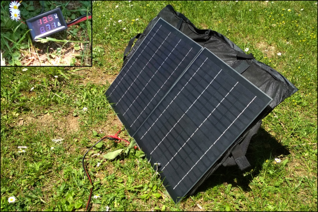
In that case we have 13.5V and 0.71A and that is 10.1W collected.
Solar Panel Placed 45º to the East
Τhe solar panels where placed turned 45 to the east, a position equivalent to 09:00 – 10:00 hours, simulating a positioned and just left there panel.

In this case we have 13.5V and 0.45A and that is 6.1W collected. This is costing the user a loss of 40% to the maximum.
Solar Panel Placed Vertically
This placement replicates the tendency of hanging one’s flexible panel on the backpack, to collect while on the move.

In this case we have 13.5V and 0.49A and that is 6.6W collected. Again a significant loss.
I am kina leery on this method, ‘cos it is not only the verticality induced losses. Οne has to assume that the hiker will be in the shadows for half of the time and turned away from the sun half of the rest of.
Accumulative losses can be expected to be 1/2 of 1/2 of the 66% to the maximum, or just 16.5%. i wonder if there is any point to it.
All in all, results were to be expected, and follow the performance calculated in this article: Solar Array Tilt Angle and Energy Output.
Alignment Tip
A twig driven in the ground can show you both the position of the sun and the proper angle for the solar panel. Just place the twig angled to where its shadow is the longest.

So, that is for now, I will have to return with more tests another time soon.
