This antenna build was inspired by Jeff’s Outdoors Page Half-Wave Dipole Antenna.
It is the same thing actually, just the materialization changes., And there is some room to improve.
But let’s start first with the build itself.
Parts Used

1. Bolts and washers, and 2 modified faucet sealing rings. The washers and the rings are installed between the two tape sections to hold their natural curvature. Then the sections are screwed on the electronics’ project box.
2 & 3. Electronics’ project box, panel mount BNC connector and ring terminals stolen from RCA and UHF connectors. This time it paid well to hoard such odd things.
4. Two sections of el-cheapo tape measure for each dipole part. The paint around the screw holes was removed for conductivity.
5. Blister packaging strips added to the dipole ends for hanging it.
6. Shoe string eyelets to fix the flexible blister sections onto the tape.
And this is how the innards of the box are assembled. Standard connectivity pattern. Tiny sections of wire soldered at the ends of the ring terminals.

BNC female panel connector. I regretted buying these, they are the opposite of the norm, thus a different cable or an adapter must be used. Better opt for a BNC Male connector.
A tip…Fix the BNC connector with some epoxy to the body. Clipping and unclipping the BNC male connector tends to turn the female one.
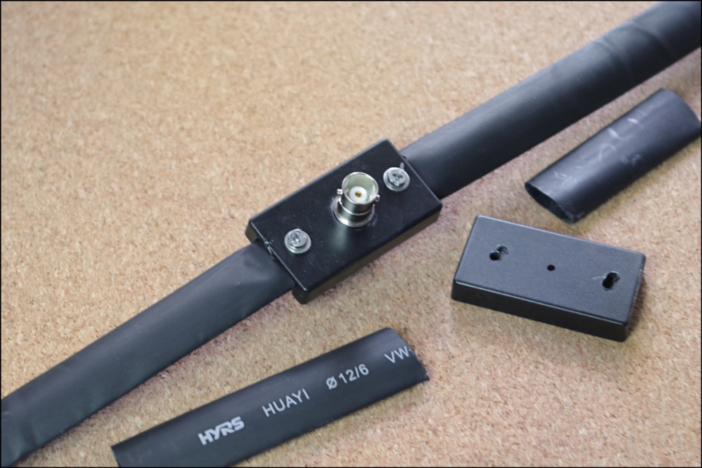
Shrink tubing is tucked inside the box opening. After the final testing and measurements it will be shrinked some, and the junction filled with gasket sealant.
BTW, the dipole ends will be finished with self sticking shrink tubing, for some measure of waterproofing.
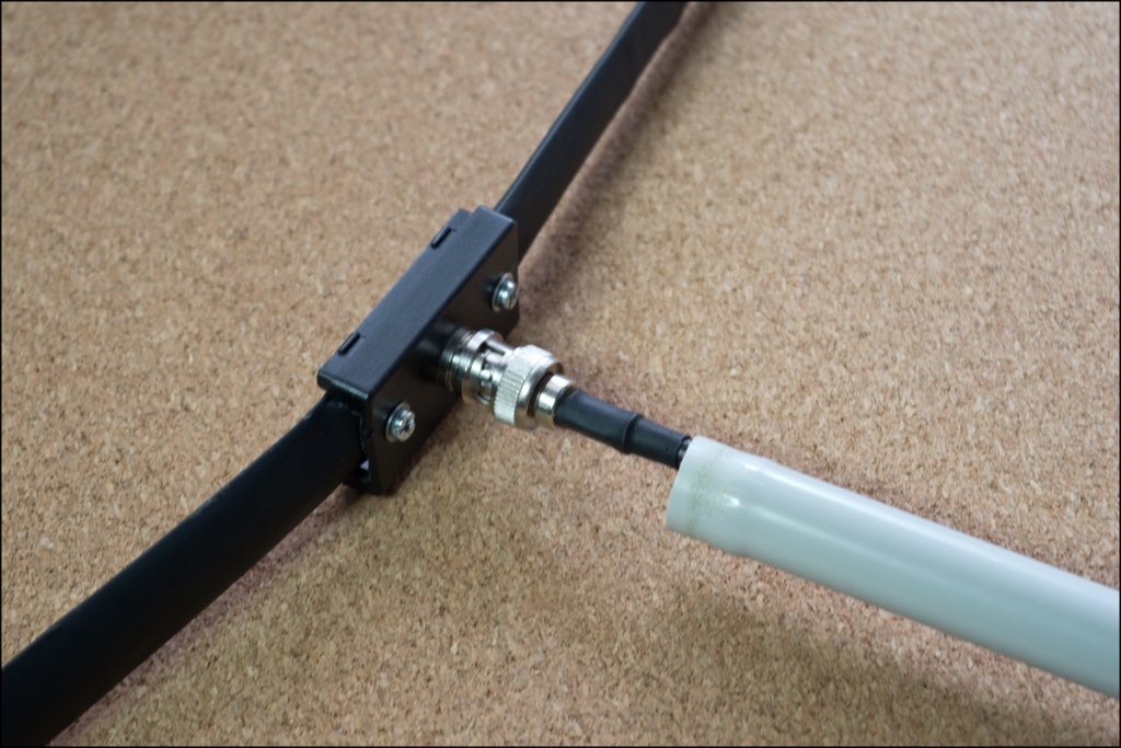
Coax wire is connected and a 16mm PVC tubing section is passed over it. Its end has been enlarged to clip on the BNC connector. This way you will be holding a 1/4 wave length of coax perpendicular to the dipole itself.
The antenna in carry mode.

Room for Improvement
I have already acquired the materials to add a balun to it. I will be following VK1NAM’s build, and building a 2nd tape measure dipole for comparison.
it will take a while , but it will happen.
Testing
The antenna was “tuned” by a SWR meter and a NanoVNA in the field.
Its final length was finalized in situ, handing from a tree at a height of 2m. Then the antenna was disassembled and re-build at home.
It is a hassle lowering the antenna, removing the shrink tubing (expected to affect performance, trim some length, reinstalling the tubing and raising it up again. And DO take care to keep the antenna vertical. NanoVNAs are marvelous ‘ cos they are showing live how an antenna’s performance changes as height and inclination is changed.
NanoVNA measurements were done with the device calibrated at the Coax End. SWR meter ones were also taken, but with the antenna on. Please take this into account when comparing the two.

That’s all.
And if you feel you got something out of this build, please share it.

Excellent build. I love that it folds up for transport. Poly orea!
LikeLike