Few days ago i took the time to “field-test” this “Tactical” Dipole… Not only I hang it from a tree, I also tried it as a backpacking antenna while hiking a short distance. It works fine, transmission RST was great.
The photos will tell the story.
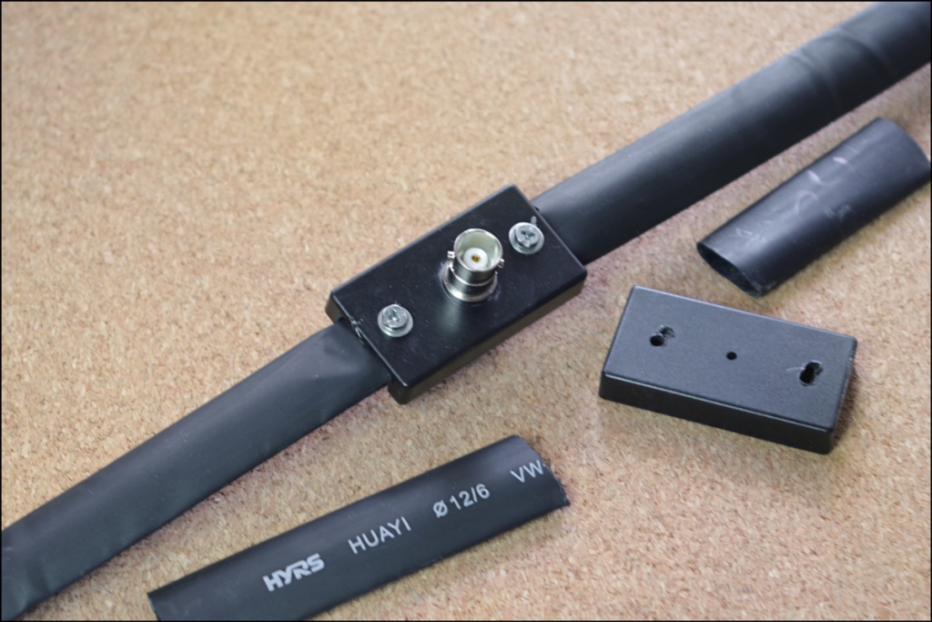
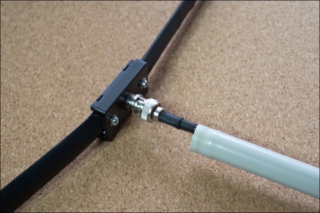
During assembly. While a stick was used to maintain the coax at 90degress to the dipole, I have already made a PVC pipe sleeve dor it, as shown at this pic.
Υeh, I know…. While part of the test was to use non-dedicated material, a few good xipties are in-order (the ties shown are the ones that hold the coax wound).
The dipole hanging… I used a Munter Hitch on the small carabiner to adjust the angle.
And the antenna mounted on my daypack. (A better mounting method must be used. Eagle-eyed viewers will notice that the antenna is attached to the packpack zipper, and it extends below the small backpack.)
That is all for now. If you liked the build, please share.
Η κατασκευή αυτή βασίζεται στην ιδέα του Jeff’s Outdoors Page Half-Wave Dipole Antenna. Ουσιαστικά είναι το ίδιο, απλά αλλάχτηκε η υλοποίηση και προστέθηκε η δυνατότητα μελλοντικής αναβάθμισης.
Αρχή με τα Υλικά
1. Βίδες, Παξιμάδια, Ροδέλες και 2 λαστιχάκια μπαταρίας βρύσης. Πέρα από την συγκράτηση των σκελών του δίπολου, τα λαστιχάκια και οι ροδέλες χρησιμοποιήθηκαν για να κρατήσουν την φυσική καμπυλότητα των κομματιών της μετροταινίας. Διαφορετικά τα σκέλη θα πάρουν μια σημαντική γωνία ως προς το κάθετο.
2 & 3. Κουτί ηλεκτρονικών. Όλα τα κομμάτια συναρμόζονται εκεί. επίσης ένας κοννέκτορας BNC για Σασί (προτιμήστε Αρσενικό), και δακτυλίδια από καλωδίων (RCA, UHF, KO).
4. Τέσσερα κομμάτια (ανά δύο) μετροταινίας. Ξεκινήσαμε με το τυπικό μήκος που δίνει ο μαθηματικός τύπος του δίπολου, αλλά καταλήξαμε στα
5. Λωρίδες από εύκαμπτο υλικό συσκευασίας. Αυτά προστέθηκαν στις άκρες του δίπολου για να μπορεί να κρεμαστεί.
6. Πρεσσαριστά grommets (κορδονιών) για την συναρμολόγηση (Κάντε τις τρύπες αρκετά μέσα ώστε να έχετε ένα περιθώριο κοπής των σκελών).
Εδώ έχουμε το εσωτερικό του κουτιού που φαίνεται η συνδεσμολογία. Tip: Μόλις καταλήξετε στη τελική κατασκευή, κολλήστε των κοννέκτορα BNC στο κουτί με εποξική κόλλα. Διαφορετικά θα έχει την τάση να στρίβει όταν αποσυνδέεται το καλώδιο μεταφοράς.
Το επόμενο βήμα είναι η κάλυψη του δίπολου με αυτοσυρρικνωμένο. Στα άκρα θα προστεθεί αυτοσυρρικνώμενο με κόλλα.
Για να μείνει το καλώδιο μεταφοράς κάθετο στην ευθεία του δίπολου προστέθηκε γύρω από το ομοαξονικό ένα κομμάτι σωλήνας PVC. Στη συνέχεια το δίπολο κρεμάστηκε από αυτό.
Και το δίπολο διπλωμένο (Φώτο από παλιότερη κατασκαφή).
Περιθώρια ΕξέλιξηςΣτο διαδίκτυο εντοπίσαμε μια κατασκευή του VK1NAM δίπολου για τα VHF που χρησιμοποιεί και Balun. Κάποια στιγμή το μέλλον θα δοκιμαστεί καθώς έχουν ήδη εξασφαλίσει τα υλικά.
Δοκιμή-Μετρήσεις
Η κεραία αναρτήθηκε σε ένα δέντρο 2 μέτρα από το εδάφους. Παρθήκαν διαδοχικές μετρήσεις ε ένα NanoVNA κόβοντας λίγο μήκος την φορά. Αφού βρέθηκε το σωστό μήκος, πάρθηκαν μετρήσεις και με ένα Στασιμόμετρο Red-Dot (μη καλιμπραρισμένο, που μετρά λίγο χειρότερα).
Σημαντικό είναι να προσέξετε το δίπολο να είναι κάθετο. Κάνοντας το λάθος να απομακρυνθώ λίγο τραβώντας το καλώδιο και δίνοντας μια μικρή κλίση στην κεραία, είδα μεγάλη διαφορά στην μέτρηση.
Αυτά προς το παρόν. Ελπίζω να βρήκατε την κατασκευή ενδιαφέρουσα.
I admit, it is the EmComm part of HAM that I am more in favor off. And while by club failed in that regard, I managed to get accredited -as an amateur communicator – by the Civil Protection Service of my Country.
The raging wildfires of this August are quite far from me, but I thought it was a good reason to check my gear and organization.
Before going any further with the pick and lists, please let me describe the core elements of my organization:
All gear is organized in Function-related kits, most of them pocket able too. All kits are self-sufficient. They do nor require parts from other kits to function. i.e. I have several devices that use USB power. well, there is a replaceable 18650 power USB power bank and charging cable for each one of them.
Each Radio comes with a better antenna AND the original stock one as a spare.
Each “Field” antenna is packed with its own coax cable.
That is not for the resiliency and the redundancy that is created, it is for the Murphy’s Law of HAMs, photographers, and maybe others. “You are going to need what you did NOT bring with you”.
So here it goes:
On Person Gear
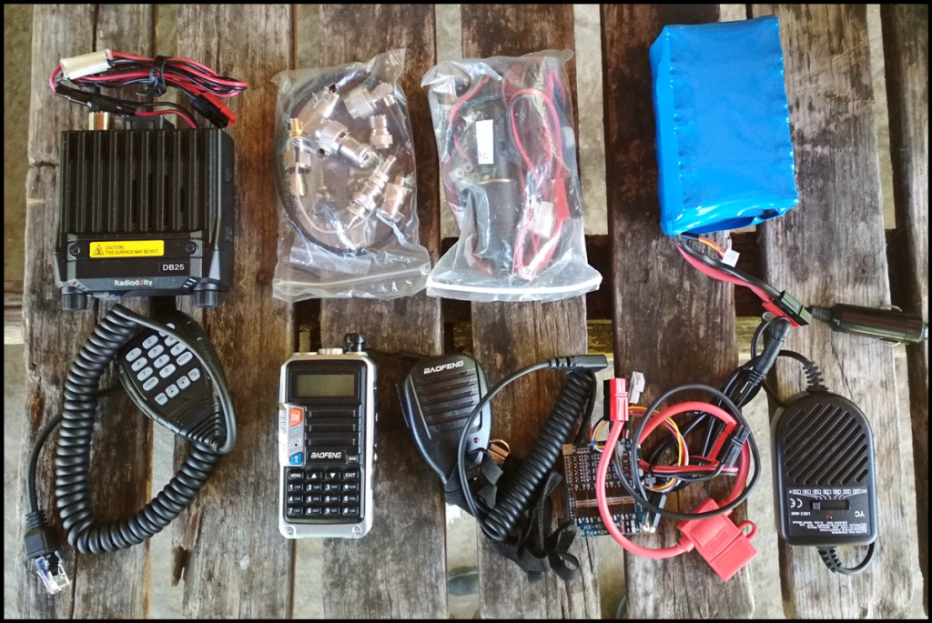
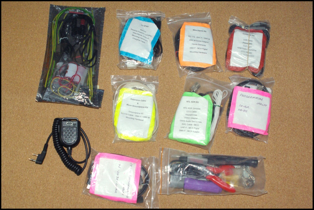
Actually this is my main handheld radio accessory and support kit. From the upper left corner:
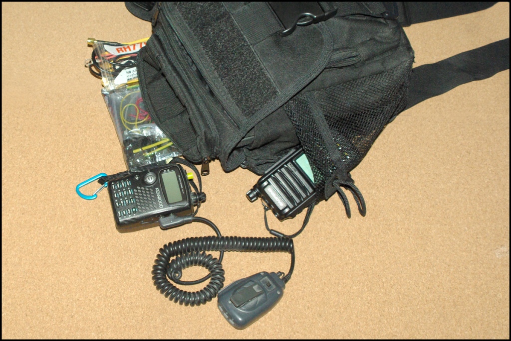
This is one step above showing up with a hand held, a better antenna, and an extra battery. It consists of the standalone prepackaged kits I talked before. It is all carried in a Jumbo Versipack Clone.
GD-77 DMR(TF-F7 in the pic) and second Analog radio (to run APRS)
Wire Dipole Antennawith screw terminal and its own coax cable and mounting hardware (screws zipties)
Το αρθράκι αυτό είναι μια αναπαραγωγή των πληροφοριών που διακινούνται σχετικά με το τις παρεμβολές στις επικοινωνίες στην Κούβα.
Καθώς η χώρα περνά μέρες ταραχών, φαίνεται ότι η κυβέρνηση έχει επιβάλει ολικό πληροφοριακό lockout, συμπεριλαμβανομένων και των ραδιοερασιτεχνικών μπαντών.
Παρόλα αυτά, Αμερικανοί ραδιοερασιτέχνες παρατήρησαν πως το σήμα των ψηφιακών modes περνούσε!
AmRRON operators on the east coast and southeast portions of the US were able to successfully exchange text messages and files using digital modes inside the affected portions of the band being jammed. The jamming did not prevent digital mode communications, which is another testament to digital modes.
It is for a fact that -crystaline solar panel perform the best when being placed vertically against the sun. That is not always possible, especially when it comes to larger units, but it only takes some effort and diligence from the user to constantly align the smaller ones.
So I tried an placement experiment, at various angles that is. Λet’s see the difference in collected sun energy…
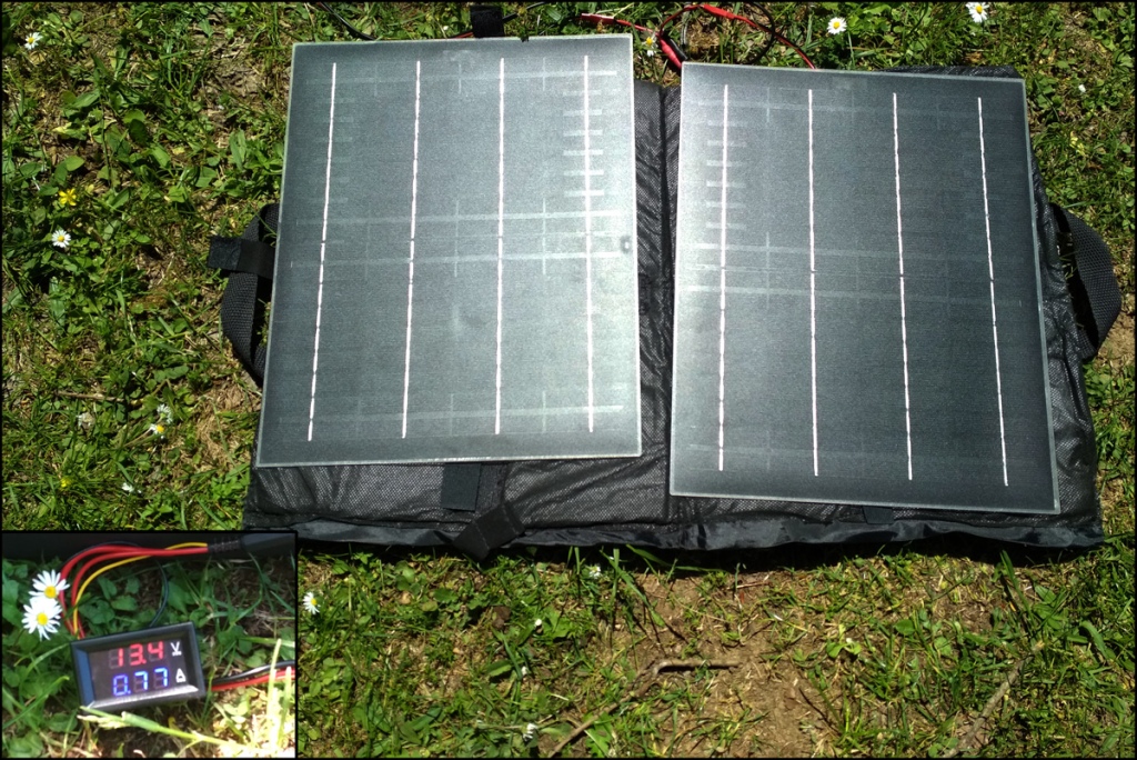
Solar Panel Placed Horizontally on the Ground
This is the lazy option for users, and an unavoidable one when it comes to camper vans etc.
At the time of the test (12:40 Daylight Saving Time) this position was close to being vertical to the sun also (maybe of a 3-5 degrees difference).
The volt/ampmeter showed 13.4V and 0.77A and that is 10.3W collected.
(please do not take this value at heart, it may be affected by my shadow when taking the meter’s pic)
Solar Panel Placed 45º Vertically to the Sun
This time the panels where placed to a 45º angle to the sun, the optimum angle for 10:00 and 16:00 hours for my location of 35º lat.
In that case we have 13.5V and 0.71A and that is 10.1W collected.
Solar Panel Placed 45º to the East
Τhe solar panels where placed turned 45 to the east, a position equivalent to 09:00 – 10:00 hours, simulating a positioned and just left there panel.
In this case we have 13.5V and 0.45A and that is 6.1W collected. This is costing the user a loss of 40% to the maximum.
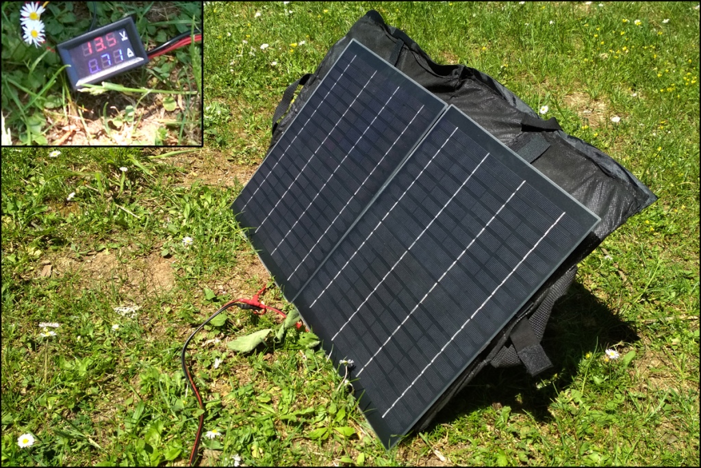
Solar Panel Placed Vertically
This placement replicates the tendency of hanging one’s flexible panel on the backpack, to collect while on the move.
In this case we have 13.5V and 0.49A and that is 6.6W collected. Again a significant loss.
I am kina leery on this method, ‘cos it is not only the verticality induced losses. Οne has to assume that the hiker will be in the shadows for half of the time and turned away from the sun half of the rest of. Accumulative losses can be expected to be 1/2 of 1/2 of the 66% to the maximum, or just 16.5%. i wonder if there is any point to it.
A twig driven in the ground can show you both the position of the sun and the proper angle for the solar panel. Just place the twig angled to where its shadow is the longest.
So, that is for now, I will have to return with more tests another time soon.
Στο άρθρο αυτό θα δούμε τις επιλογές κεραιών που έχει ένας ραδιοερασιτέχνης που είναι ταυτόχρονα και survivalist ή prepper. Ειδικά στην περίπτωση που δεν έχει τα τεχνικά μέσα ή τις τεχνικές ικανότητα να φτιάξει “και να συντονίσει με όργανο” αυτοσχέδιες κεραίες.
Φυσικά όλες του τύπου οι κεραίες είναι εμπορικά διαθέσιμες, αλλά αυτό δεν σημαίνει ότι σε περιπτώσει ς ανάγκης θα είναι δίπλα του. Οπότε θα πρέπει να υπολογίσουμε και σε ένα παράγοντα αυτοσχεδιασμού.
Επίσης στην περίπτωση που εξετάζουμε, μπαίνουν και άλλα κριτήρια. η φορητότητα, η διακριτικότητα, η ευκολία χρήσης από όλα τα μέλη της οικογένειας του, κτλ.
Μια Καλύτερη Κεραία για το Φορητό μου
Η κεραία που συνοδεύει τον φορητό ασύρματο είναι γενικά ανεπαρκής και απλά δουλεύει . Αν θελήσουμε να αυξήσουμε την εμβέλεια του τότε θα πρέπει να πάμε σε μεγαλύτερη κεραία.
Η μία λύση είναι να αγοράσουμε μια κεραία μαστίγιο (προτείνουμε 40 με 50 cm μακριά). Τα συνήθη μοντέλα είναι τα Diamond SRH229, Diamond SRH77CA, Nagoya NA-771, Nagoya NA-761 & Nagoya NA-24J
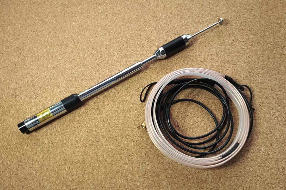
Το επόμενο επίπεδο είναι η χρήση μια τηλεσκοπικής κεραίας. Σε χρήση είναι άβολη, αλλά το άλλα στην απόδοση είναι μεγάλο.
Καθώς όμως οι κεραίες δεν είναι μόνο ένα κομμάτι σύρμα αλλά απαιτούν μετρήσεις με όργανο και συντονισμό, το να φτιάξουμε μια κεραία ανάγκης περιορίζεται στην επαναχρησιμοποίηση τυποποιημένων εμπορικών κεραιών με διαφορετικό τρόπο.
Αυτός που προτείνουμε είναι να μετατρέψουμε την βελτιωμένη κεραία του φορητού ή την κεραία του αυτοκινήτου σε κεραία βάσης τύπου groundplane.
Αυτό γίνεται με την υποκατάσταση του groundplane, είτε παρεμβάλλοντας μεταξύ της κεραίας και του καλωδίου ένα κιτ με radials (ακτινωτά στοιχεία), είτε με μια ανάλογη αυτοσχέδια κατασκευή.
Nagoya RE-02, ένα έτοιμο και οικονομικό κιτ radials.
Ένα αυτοσχέδιο σύστημα radials με την χρήση ηλεκτρικού καλωδίου και κοννέκτορα.
Μια ακόμα πιο εύκολη κατασκευή είναι με την χρήση μιας μαγνητικής βάσης για κεραία αυτοκινήτου (mobile).
Σε αυτή την περίπτωση καρφώνουμε σε ένα κοντάρι μια λαμαρίνα ή ένα ταψάκι για να εξομοιώσουμε το “τεχνητό έδαφος” (groundplane) και απλά τοποθετούμε την μαγνητική βάση με την κεραία μας
So. it was a long without a proper battery pack to feed my mobile during field conditions.
For a short time I made do with a 4S 26650 LiFePo4 on battery trays, which afforded me the simplicity of charging the batteries in a battery charger.
But that affords no great runtime, so I opted for TWO packs, one for working filed, and the other being charged by solar panels.
The materials used. The red board is the MPTT solar charging board, with its 5.5×2.1mm DC leads.
The build is straightforward, put the batteries on battery clips and bridge accordingly.
In my case, I opted for soldering the batteries together. Half of them were simple standalones and half of them were purchased with Z tabs, tabs pointing at opposite ways.
While soldering is not a recommended method, it was easy to do by using nickel strips which were drilled through. A blob of solder on the battery contact melts easily again and catches both below the stip, and around the hole.
Right where the yellow wire is soldered you can see the drilled nickel strip.
Using the same idea I soldered the power wires with the same method. I first crimped ring terminals on them and then soldered them on the battery contacts (see at the green arrow). Nice and easy.
The BMS monitoring wires were soldered too and they were made tidy by shrick tube and by passing them through holes on the battery clips.
And this is the jumbled mess of the 30A BMS control board. Yet there is logic in the madness!
What is in the Future.
Both boards will be heatsinked and placed each in a seperate box. And amp/volt meter, a 30A breaker and a switch will be added on it…
There is one (more) new addition to the Baofeng line of handheld radios, the UV-S9, also known as UV-5R Pro.
As expected, it is a new shell on an UV-5R, but with a few improvements.
As expected, it is a new shell on an UV-5R, but with a few improvements.
Improved aesthetics, new colors (Red and Silver and Yellow) which become to it, and a new key layout.
Battery capacity is 2800mAh, and the radio can be had in high power, triband, and high power AND triband versions. (I am hesitant to suggest a purchase link, but Alliexpress and Ebay are full of them).
The Triband versions of the radio are usually shipped with two short antennas by retailers. I measured both at 1.5 SWR, which it is OK, especially considering that fake antennas log at very high numbers.
But most importantly a charging socket has been added to the battery shell, much like the one on the extended UV-5R battery.
Which is a huge step forward, cos one can now charge the radio in the field, without use of the charging cradle.
The socket accepts a 9V DC current, (nominally 7.2/8.4V) through a 3.5×1.35mm plug.
As far as I can tell it is a straight connection to the battery with no charging chip in the circuit.
So be careful of what kind of power you hook up in there. A 12V cord is available but I cannot vouch for it, as it seems it lacks any charging circuitry.
The USB to DC power cord is good though, and draws 0.7Amp from the USB power source.
So what keeps it from becoming a proper amateur/hobby radio?
The alarm and the flashlight of course…Though the alarm can always be muted through the software.
And there is one more thing I find annoying. The reverse position of the up and down arrows. I mean, we westerners are used to have such arrows the other way around. Left for down and Right for up. Anyway…
And since firmware has been mentioned, the -S9 can be programmed through the BFB291 version of the -5R firmware, and CHRP recognizes the triband version of, as the UV-5X radio.
Χθες έτυχε να τελειώσω αρκετά νωρίς απο την δουλειά, και έχοντας τον χρόνο είπα να απολαύσω τις τελευταίες καλές μέρες στο βουνό, αλλά με δημιουργικό τρόπο.
Οπότε πήγα στο σύνηθες στέκι μου, και δοκίμασα να χρονομετρήσω πόσο γρήγορα μπορώ να στήσω επικοινωνίες με τα υλικά που έχω πάντοτε στο αυτοκίνητο.
Μέσα σε ένα λεπτό είχα μεταφέρει τα υλικά από το αυτοκίνητο και μέσα σε τέσσερα ακόμη είχα στήσει και τον δεύτερο ασύρματο.
Χρειάστηκαν σχεδόν άλλα έξι λεπτά για αν συναρμολογήσω την αντένα πεδίου, να κρεμάσω από ένα κοντινό δέντρο και να την συνδέσω.
Μια ματιά στο πως συναρμολογείται το “τεχνητό έδαφος” για την grounplane αντένα του αυτοκινήτου.
Και τέλος μια ματιά στα περιφερειακά υλικά ασυρμάτου. Ομοαξονικά καλώδια, αρτάνες, ανταλλακτικά βύσματα, αντάπτορες κοννεκτόρων, υλικά στερέωσης, τροφοδοτικά 12V & USB και άλλα.
Κλείνω με μια παρότρυνση. ΔΕΝ είναι δύσκολο να δοκιμάσεις την ετοιμότητα και την καλή λειτουργία των συστημάτων ασυρμάτου σου. Θέλει λίγο χρόνο αλλά και απόφαση να ξεβολευτείς λίγο. Αν το έχεις στο νου σου, βρίσκεις τις αφορμές και ευκαιρίες…